|
Designing for Interference-free Audio System Components By Tony Waldron, Technical Manager, CADAC Electronics PLC
Table of contents 1 Synopsis 2 Introduction 3 Radiated emission tests 4 Conducted emissions 5 Radiated Immunity 6 Conducted Immunity 7 Conclusion
1 Synopsis As a student technician I would spend several days each month helping experienced engineers to minimize the noise in and around an audio mixing console system prior to it’s final test. Despite the fact that fully tested modules worked satisfactorily on the bench, they behaved quite differently when connected together in a console frame. The main interference problems fell into the category of hum or buzz. This was dealt with by a process called “finding the hum loops”. Unfortunately the hum loops would often disappear and then reappear unexpectedly with a different timbre. Even when all the different hums and buzzes were eliminated, clicks or other spurious noises would then be revealed and the search would continue until minimum noise was achieved. The same fun and games would start all over again when the console was delivered to the customer. A small army of engineers and technicians would swarm all over the studio equipment in a search of a different set of hum loops.
In recent years I have discovered this was all unnecessary. Because of a design decision made many decades ago, possibly even for no very good reason, and repeated as if it were gospel ever since, all audio mixing consoles and similar equipment has been condemned to hum and buzz with lengthy ‘fiddling about’ to solve the problems. It took the introduction of digital technology, and the EMC directive with its professional audio EMC standards EN 55103-1/2, to force us to abandon our decades-old practices. We were surprised and gratified to discover that our new design techniques save time and money, eliminate hum and buzz problems once and for all, and improve audio performance.
2 Introduction Avoidable interference has probably caused more time consuming and therefore expensive problems to occur in audio system installations than any other form of system fault. Until comparatively recently, my own audio system education had led me to believe that interference in an audio system was unavoidable, but the effects of it could be mitigated by the careful use of a specific set of incantations known only to a few Audio Druids. Such gentlemen could be engaged to recite the appropriate words for a large fee. Indeed, I learned the most famous incantation myself – “connect the cable shield at one end only”, and applied it on many occasions – sometimes successfully and sometimes not. With hindsight, the most amazing aspect to system interference is that so many professional engineers seemed perfectly content to run around in circles, chasing hum, buzz and clicks, year in and year out, without actually discovering a final solution to the problem that would ‘work’ the same on every occasion. Instead, we ended up with a collection of deeply held beliefs and prejudices that owe much more to folklore than to the physics underlying the problem. We are well rid of them.
In the early 1990’s, the micro-electronic revolution delivered a new and more direct form of interference to the studio and live sound stage - computers, computer assisted equipment, and cell ‘phones. This turned out to be a very positive move for a number of reasons, not the least of which was that a whole new set of electronic system design professionals became available to help solve interference problems in general. At the same time, national and international standards bodies began to realize that some form of control was necessary to prevent wholesale pollution of the airways by the ever-increasing processor speeds and hand-held interference machines. This combination of events led many of us to take a fresh look at the underlying physics of audio system engineering.
The first indication that rules actually existed for interference control, based firmly in fundamental physics, came to me at a seminar organized by the AES and presented by Ralf Morrison. The revolutionary idea that audio engineering could benefit from knowledge of grounding and shielding techniques designed for instrumentation and RF systems was at once exciting and problematical. Excitement at the prospect of a possible solution, marred by the fact that I had flunked off from the lectures on RF at University, because I had considered the subject non-applicable to an audio engineer (it was a long time ago).
At about the same time, the European Economic Community (EEC) announced rules and regulations to force manufacturers and distributors of electronic equipment to limit the amount of electromagnetic radiation that an apparatus was allowed to emit or be susceptible to. The regulations would be based on the National Standards of each country in the EEC, “harmonized” so that the rules would be the same in each member state. The regulations would come into force on the 1st of January 1996. In the meantime, seminars would be arranged by National Standards bodies to provide education on the new topic of Electro-Magnetic Compatibility (EMC). One of the presenters at the very first EMC seminar that I attended was Keith Armstrong. Thus began a long and fruitful relationship that has already resulted in excellent EMC designs for audio equipment and systems and a joint article on how to connect cable shields in audio systems [12].
Electromagnetic disturbances can be classified into four types of phenomena: radiated low frequency; radiated high frequency; conducted low frequency; conducted high frequency. Thus, EMC would cover emission and susceptibility problems in equipment and systems over the frequency range of a few hertz to many GHz. This meant that problems and solutions of a RF nature had to be considered at the same time as low frequency phenomenon. Since the considered wisdom of the time held that RF solutions did not sit very happily with the low frequency problems found in many electronic systems, there was much opposition to the draft regulations and the suggested test methods. Opposition from the audio industry continues to this day, despite the valiant efforts of a number of AES members, who contributed to the AES Journal Volume 43, Number 6. [1]. This is great pity, because the control of interference has become an essential part of system engineering and design. Even in countries where there are no laws and regulations on EMC, the control of EMC results in financial benefits for both suppliers and users. The “Protection Requirements” described in the European EMC Directive are nothing more than good engineering practice. On emissions, the relevant harmonized standard is to protect radio reception outside of the designer’s control, unless there is very sensitive apparatus nearby, which makes even lower levels of emission necessary. The immunity part of the standard is to ensure that individual apparatus and system interconnections can function with adequate performance and reliability in their intended environment.
Learning what to do to meet the EMC Directive opened my eyes to the fallacies of the time-honoured design techniques, and showed me the way to design audio consoles that were naturally free from hum and buzz, much less labour intensive to assemble and much easier to install. To show you how I came by this, to me, revolutionary insight, I’ll describe the main EMC tests required by the EMC Directive, the results we achieved with our traditionally-designed consoles, and the process by which we learned to design them properly. All of these techniques are now clearly set out in the book EMC for Systems and Installations by Tim Williams and Keith Armstrong [4].
The product specific EMC standards for the audio industry are EN 55103-1 [5] for emissions and EN 55103-2 [6] for immunity. Product specific standards employ a number of basic EMC standards that set out the test methods used to evaluate the equipment under test. The test apparatus used to perform the tests must meet some basic minimum standards, as laid down by the IEC and CISPR (figure 1).
2 Emissions Radiated low frequency phenomena - emitted by audio equipment - is generally confined to local magnetic fields generated by power supply components. Stray magnetic fields produced by the mains transformers in high current linear power supply units, can and do cause VDU screen wobble (CRT types).
Continuous radiated interference at high frequencies is unusual in analog audio equipment, although some operational amplifiers are known to produce emission well outside their design bandwidth. But audio equipment designed to work with digital control circuits is a very different matter [2, Chapter 6]. Copious amounts of continuous radiation are found to exude from almost every wire and aperture, the moment a processor is included in a design. The frequencies radiated start at a few kHz and are almost continuous to many hundreds of MHz. This is a much more serious problem, because of the interference potential to the audio circuits they serve. The interference will be exacerbated, if the audio and digital circuits are physically close together, or in the same box.
At system level, emissions are always a possibility wherever the length of a conductor is a significant fraction of the wavelength of the radiated frequency. AC mains supply cables can distribute interference by both radiation and conduction, and are under threat from induced voltages and harmonic distortion from equipment power supply units.
3 Radiated Emission Tests Radiated emission tests require a measuring receiver and it’s specifications are defined by CISPR 16-1 [3]. The CISPR receiver specification parameters are summarized in table 1. The specification also covers the type of detector required – peak, quasi-peak or average. Table 1CISPR measuring receiver requirements
Measuring receivers are extremely expensive, which is partly due to the unusually severe specification that is placed on their linearity and amplitude accuracy. Luckily a less expensive alternative is allowed in the form of the spectrum analyzer. Several suppliers now produce a version of their standard model, specifically for EMC use. Such analyzers have the correct CISPR bandwidths and detector built in.
Commercial antennas able to detect and convert the incident field strength covered in Bands A to D come in three types:
· loop, for the range 9kHz to 30MHz (Bands A and B). For the few standards that require magnetic field tests, the limits are quoted in dBmA/m · biconical, log periodic or Bilog are used for the range 30MHz to 1GHz (Bands C and D). Electric field strength limits are quoted in dBmV/m · horn, for frequencies above 1GHz (some log periodics and Bilogs can be used up to 2GHz. Electric field strength limits are quoted in dBmV/m
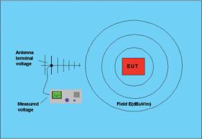
The most important property for EMC measurements using an antenna is the antenna factor. A calibrated broadband antenna is supplied with a table showing its antenna factor versus frequency. The graph applies to an incident field in the same plane of polarization as the antenna, its terminals loaded with its specified impedance. In most cases, a cable is used to connect the antenna to the measuring device. Since the attenuation of the cable is frequency dependant, the cable loss (or cable factor) must be taken into account. For the test set up shown in figure 2, the true field strength detected (E) is given by:
E dB(mV/m) = V dB(mV) + AF (dB/m) + [A (dB)] (1)
where: V = measured voltage AF= Antenna factor A = cable attenuation factor
The radiated emission compliance tests set out in CISPR 11 describe the performance and features required for an Open Area Test Site (OATS) with a defined site attenuation characteristic and fixed distance measurement antenna. The accompanying complex features and procedures mean that tests of radiated emissions according to the standard require a fair degree of skill and familiarity with the standard. Changes recently made in CISPR 22 (EN 55022) allow meaningful measurements to be made in a screened room (sometimes called a shielded chamber), at least for the purposes of assessing and comparing the results of design changes. In fact, it is possible for most companies to achieve in-house measurements which are good enough when following the self-declaration route to compliance with the EMC Directive, without spending a great deal of money. But, if following the Technical Construction File (TCF) route instead, the quality of the test evidence that will be required should first be discussed with the Competent Body who will be assessing the TCF.
A draft amendment to CISPR 22 relating to user installation testing was circulated in 1998 and there is now a proposal to standardize an alternative method to the OATS using a fully anechoic room (FAR). At the time of writing, no standard has been published.
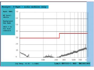
The radiated emission tests referred to below were performed in a screened room, using test methods as set out in EN 55022 [9]. Inside a shielded enclosure, it is immediately obvious that the amount of radiated emissions from analogue audio circuitry, assembled as a complete sub-system, is extremely low in the frequency range required by the standard - 30MHz to 1GHz. Figure 3, shows the emissions from a 32 input 8 output analogue audio mixing console, with I/O cables connected and terminated to represent a typical installation and operating mode. The receiving antenna was placed in the far-field. This is a scan with the antenna in vertical polarization. There was very little difference in radiated emissions with the receiving antenna in horizontal polarization. In this 1994 production model, I/O cable shields were connected to the PCB 0V trace in every module. The chassis was isolated from signal reference ground. In other words, the console had the “pin 1 problem” [1].
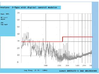
The same console frame was then stripped of its analogue-only modules and re-populated with 32 input channels and 8 group modules fitted with digital control circuits to allow programmable switching and level control. A Central Control Module containing one interface processor and one communications processor is also required with this version of the audio mixing console. The clock speed of the processors was 16MHz, with switch, level and other data collected and delivered using two 500 bit/sec serial data buses. All I/O cables were connected and terminated as in the previous test. In normal use, this type of audio mixing console system would be used with an external computer for data storage and recall, but in this test, the external computer was not connected.
Even so, scans in the frequency range 30MHz to 1GHz revealed high levels of emission from 30MHz to 300MHz (figure 4). Peaks associated with the 16MHz clock-frequency were very obvious and many had amplitudes well in access of the EMC standard’s limit line.
When the console frame was rotated, the emission peaks increased by some 10 dB. The rear of the console contained all the I/O connectors and this result indicated that the audio I/O cables could be involved in the emissions. Emissions were even worse when an external computer was connected to the console.
When the audio I/O cables were disconnected, the emission peaks decreased by some 10 dB, but emission from the rear of the console was still greater than from the front. It turned out that all cables connected to the console, including cables for the power supply and console lights, were involved in the radiation of the digital clock and processor bus noise. It also seemed that the aluminium frame and module panels did not provide much of a shielding effect at these frequencies. Could it be that the very small gaps between modules allowed the internally generated RF out? To test this, the top of the console was covered with a conductive material – nickel-plated nylon rip stop (a material used for the manufacture of EMC shielding tents). When the nickel-plated nylon rip stop was connected to the chamber ground plane in several places, the emissions decreased by a further 10 dB. The small gaps between modules were effectively a slot antenna array!
We know that: c = l.f (2)
With a slot length of 600mm (23.6”), the gap between modules represented a quarter wavelength antenna array at 125MHz. However, the radiated emissions from cables connected to the console proved to be a much more serious problem. It is now well understood that cable or chassis slot lengths of even 1/10th of a wavelength of the generated frequency will radiate and cause RF interference problems.
Near field investigations, using electric field and magnetic field probes, revealed that:
(i) printed circuit boards containing digital control circuitry produced high levels of wide band radiation;
(ii)noise currents with a similar frequency range was induced in other circuits and conductors in the system, including the power bus;
(iii)shielded and unshielded cables connected to I/O connectors carried the same noise frequencies away from the console;
(iv)the structure of the console did not provide enough shielding effect for the internally generated frequencies.
At audio frequencies, the noise performance of the console was extremely good, although noise from the digital processor circuits could just be heard in the noise floor. Now we knew why! Another significance of these findings was that the console could very easily interfere with it’s own digital control circuits as well as with adjacent equipment!
The first rule for interference free design is to minimize the problem at source. All digital control circuit boards were re-designed:
· taking great care with component layout (segregating noisy circuits from quiet ones); · assuring that chip de-coupling actually worked at high frequencies; · minimizing the length of noisy traces; · being careful with the routing of noisy traces; · using ground and power planes.
[2, chapters 5, 6, 7].
These changes were made as much for minimizing the possibility for self-interference as minimizing the overall emissions for compliance. As the new circuit boards became available, near field probe testing indicated that the interference fields were significantly reduced.
Improving the shielding effectiveness of the console structure was not so intuitive. Techniques and accessories for sealing up the gaps between modules and holes/slots in panels were available, but the large number of holes and slots required in the front panel of an audio control module and the modularity itself, tend to reduce the shielding effectiveness rather severely. Modular structures with many holes and slots must be considered to be poor for shielding purposes. From an EMC perspective, the most important aspects of a metallic enclosure is:
· to provide a local ground reference for the internal equipment; · to provide and demarcate a zone of increased EM protection; · to prevent radiated field coupling to and from the internal equipment.
This does not mean that a metallic shielding structure is not important for interference control, but that the lack of total shielding integrity requires a very different approach. A well known RF technique is to mount all I/O connectors on a single conductive plate that is bonded to reference ground [4, chapter 6]. For this to work effectively as an interference bulkhead, all cable shields must bond to the plate – a large area of grounded conductive plate gives an extremely low transfer impedance, assisting interference currents to return to their source with minimum impediment. This meant that the internal grounding scheme for the whole console had to change. The grounding scheme used on the original design was the star technique. Star grounding is very effective at very low frequencies (a few tens of Hz), but as frequency rises, single point connected conductors are progressively de-coupled from ground. Despite much opposition from the rest of the design team, mesh-grounding techniques had to be considered.
Historically, isolated ground conductors had been included for each type of circuit in the console system. It was normal for a console to have one isolated ground conductor for the audio power supply, and a second isolated ground conductor for the logic circuits. The argument was that the ‘dirty’ logic ground must be kept separate from the ‘clean’ audio ground, or the ‘clean’ audio ground would be corrupted. Sometimes two logic ground conductors were included – one for the really ‘dirty’ circuits associated with digital processors and one for the less dirty circuits comprising slow-switching logic gates. This technique was accompanied by much fiddling around to find the right place for the single star point for all the ground conductors in order to achieve minimum noise in the audio circuits. There was total uproar when I suggested that all ground conductors should be connected together at every available point on the circuit boards and to the console frame, to produce a mesh ground.
The main objection to mesh grounding techniques is that a large number of “loops” are created. At very low frequencies, current loops and their associated driving potentials, are well known to be sources of interference that can be identified with hum and buzz. When the loop is broken, the current is zero, and the interference disappears. Unfortunately, the potential differences that drive the interference currents remain, so that interference can return if a loop is closed in another part of the structure - on purpose or by accident. Low frequency loops tend to have very large areas that are rarely under the control of the system designer. Loops produced by a mesh can have relatively small dimensions by design. When the mesh loop areas are made small compared with the wavelength of the interfering radio frequency, their interference potential is very much reduced, and happily their potential for creating low-frequency hum or buzz is also dramatically reduced.
In practice, any loop has a resonant frequency and will tend to act as an antenna or a poor earth/ground bond at that frequency. Thus, mesh techniques work best when the mesh size is varied – producing a large number of low impedance paths to ground over a wide frequency range. Mesh ground techniques put the designer in control of the interference current return paths [2, 4, 7, 12].
In one respect the ‘old guys’ were right – one loop (or a few large loops) could be bad news for hum and buzz. However, single-point grounding cannot control RF interference, whereas mesh grounding can. So we have to move from the traditional idea of having no loops, to having a large number of small loops. There is no middle way.
In the re-designed console, all audio and digital control I/O ports were filtered. Balanced I/O ports were provided with bifilar inductors wound on a common ferrite core. The balanced audio input ports had additional capacitors connected on the circuit side of the inductors and referenced (bonded) to the chassis. In this configuration, incoming and outgoing common mode interference should be absorbed in each direction. The few digital control I/O ports that were still unbalanced (at that stage of circuit development) could only have differential mode filtering applied. This is still a potential problem, because filtering techniques only work properly when the filter is designed to work in the correct mode (a common mode filter will have very little effect if the interference is differential mode and vice versa) [4, Chapter 8].
All of the principles discussed above were applied to the console structure before the system was re-tested. A summary of the most basic changes made was as follows:
(i) All I/O connectors mounted on a continuously conductive backplate with all connector cable shield connections bonded to the metalwork. This, to provide a low impedance ground for signal reference.
(ii)The backplate bonded to the rest of the console frame, so that when all modules were in place, the internal circuitry was provided with a shield which provided a useful amount of shielding effectiveness up to approximately 100MHz (based on the length of the longest slot in the structure).
(iii)Internal ground conductors mesh-bonded to the backplate.
(iv)All signal and control I/O ports filtered.
(v) All module printed circuit boards re-designed to properly segregate noisy and sensitive circuits. Wherever possible, continuous ground and power planes were included. Ground and power planes reduce current loop sizes dramatically and reduce H-field emissions plus they provide a ‘solid’ RF ground reference for filters and decouplers. Particular attention was given to de-coupling components and layout around all IC’s. Four layer printed circuit boards were found to be necessary in many cases, with one whole layer used exclusively as a ground plane.
(vi)Filtering also applied to AC and DC power inputs and outputs.
The radiated emission tests already described were repeated in several stages. Emissions from the console with no cables connected (except for the power cable) were well under the limit line. As each cable was connected to the console, a new scan was performed. Adding additional I/O cables produced an ever-increasing level of emissions, with many unexpected culprits revealed.
· The cable feeding the variable dc voltage to the console lights radiated copious amounts of clock noise. This was reduced to negligible proportions when the 0V return conductor was mesh bonded to the console back-plate. · The unbalanced headphone extension cable radiated clock noise. While one end of its shield was bonded to the console’s back-plate, the other end was isolated from ground by the use of an insulated jack socket. The headphone extension cable thus had a different potential at each end of its 0V conductor allowing the return conductor - the cable shield - to act as an antenna. The radiation disappeared when the insulated jack socket was replaced with one that bonded the shield connection directly to the console metalwork.
Figure 5 shows the worst case emissions from the rear of the modified console, all I/O cables connected and terminated, as in the previous test. The average reduction in emissions was some 20 dBmV/m in the range 30 to 400MHz.
4 Conducted Emissions It was clear from the initial radiated emission tests that if the circuits were capable of generating any amount of RF energy, the signal could appear at the I/O ports. This means that internally generated interference can be passed on to other equipment via interconnecting cables. Conducted emissions measurements are commonly made on the mains supply port of the EUT. This is because the mains supply offers the most direct route for conducted disturbances to reach other mains-powered equipment, and because the mains supply wiring is an efficient radiating antenna at the frequencies of the conducted tests.
Figure 6 shows the basic test set-up suggested for investigating the live or neutral line with respect to ground. The test limits for the appropriate CISPR based standards are published in EN 55022 [9]. There are four significant parts to the circuit: the Artificial Mains Network/Line Impedance Stabilizing Network (AMN/LISN), the EUT, the mains cable between the two, and the ground reference [4, chapter 10, page 246]. The requirements of the AMN/LISN are defined in CISPR 16-1. One very important aspect of using the AMN/LISN is that its ground reference conductor must be solidly bonded to the ground plane that forms part of the test set-up.
The resultant interference levels can be monitored using the same spectrum analyzer as for radiated emissions, but it is essential to use a transient limiter in series with the voltage probe to avoid damage to the analyzer’s input circuit. Figure 7 shows the high levels of interference that can be involved. Although this is a particularly bad example, it will serve to demonstrate the problem areas. The EUT was equipped with a commercially available switch-mode power supply unit designed before the EMC regulations came into force.
The harmonics generated or processed by the power supply circuit can be clearly seen right across the test frequency range 150kHz – 30MHz. Some additional peaks and nulls at the low frequency end (150kHz to 400kHz) are due to rectifier switching. Rectifier switching interference also shows up in linear power supply units. Some of the energy above 1 MHz was found to be attributable to clock noise from the load circuit.
The offending apparatus was contained in an aluminium enclosure, but the enclosure was not bonded to the protective earth conductor of the AC mains supply cable. This fact alone made the unit illegal, but for EMC, there was nothing to provide an adequate ground reference for the internal electronic circuit. When the protective earth conductor was bonded to the enclosure, the amplitude of the switching transients on each power input line was much reduced.
Power line filters are available specifically for controlling conducted emissions, but making the right selection for such a filter can prove to be problematical. The performance of any filter depends on the impedance seen at its terminals. The impedance of the AC supply can vary from a few ohms to several thousand ohms. This depends on the loads connected to it, the nature of the supply transformer and the wiring to the supply outlet. The impedance of the AC/DC converter (rectifier) varies from a few ohms to some millions of ohms. This rules out the use of single stage filters since their performance is unreliable under varying input and output impedance conditions. Single stage filters can produce gain rather than attenuation, but filters designed with two or more stages are able to maintain an internal circuit node at an impedance that does not depend too much on input and output impedance [4, Chapter 8]. Such filters are, of course, more expensive than single stage devices.
Manufacturers of high performance line filters publish the differential mode (symmetrical) performance data for both “matched” and “mismatched” source and load, in accordance with CISPR 17 [10] requirements. These performance figures are usually shown graphically as filter attenuation versus frequency, where matched impedance means a 50 ohm source and a 50 ohm load. “Mismatched” means 0.1 ohm source, 100 ohm load, and vice versa. From these data it is possible to estimate the performance of a given filter.
It was decided to redesign the power supply unit. The modified unit had the following properties:
· Power supply circuit components contained in a steel enclosure. · AC power input lines filtered using a two-stage line filter. · AC power input protective earth conductor bonded to the steel enclosure at the point entry (for safety and EMC considerations). · 0.1mF capacitors connected in parallel with each diode in the bridge rectifier. · All internal circuit ground conductors mesh bonded to the enclosure.
When the unit was re-tested to the requirements of EN 55022, all emissions were shown to be greatly reduced (figure 8). The low frequency emissions (below 1MHz) proved to be well under control. This was due to the use of the AC input line filter, the capacitors in parallel with the rectifier diodes and the grounding structure. The still relatively high emissions in the region 2MHz to 7MHz were caused by the digital control circuits in the console. Improved filter techniques for digital signal I/O ports was found to be necessary and in some cases, digital I/O cables had to be equipped with cable mounted ferrite clamps [4, chapter 8]. When this was corrected, the power supply unit and its load (the mixing console) passed the conducted emissions test with a good margin.
5 Radiated Immunity The basic feature of an immunity test is that the EUT is subjected to external interference phenomenon generated by the test engineer and its performance monitored for unusual or unacceptable operation.
EN 55103-2 requires that the following conducted and radiated immunity tests be carried out on audio equipment:
(i) Electrostatic discharge: a source of transient upset typically occurring when a person or other body that has been charged to a high potential by movement across an insulating surface then touches an apparatus connected to ground, thereby discharging through the equipment. Currents of tens of amps can flow for a short period with a very fast risetime (often sub-nanosecond). Although the energy may be low and conducted to ground through the equipment case, such current pulses couple very easily into the internal circuitry and can disrupt its operation.
(ii)Electrical fast transient bursts: the repetitive ignition and extinction of an arc discharge caused when a current carrying circuit is interrupted by an unsuppressed air gap switch (such as a contactor or relay). Although fast switching transients have low energy and are only a threat to local susceptible equipment, there are many sources of such transients in a typical electrical installation. Fast-rise events have considerable upset potential for digital circuits, and equipment reliability will be enhanced, by taking them into account.
(iii)Surges: high energy transients as a result of lightning coupling to the supply network or due to major power system disturbances such as fault clearing or capacitor bank switching.
(iv)Radiated and conducted RF: the susceptibility of an apparatus to direct interaction of the EM field with the circuit wiring, printed circuit traces and even the IC sockets and lead-frames inside the equipment enclosure; and the induction of common mode currents onto cables which are then coupled into the internal circuits by conduction through the cable port interfaces.
The problem of radio frequency immunity testing has become an extremely controversial subject, and has produced more debate than any other phenomenon in the field of EMC. Such tests are certainly necessary, since the proliferation of portable and fixed radio transmitters, with field strengths high enough to upset electronic equipment, increases every day. Unfortunately, the standard test methods for radiated immunity are expensive to do, mainly because of the difficulty in developing a uniform calibrated radiated field at the lower frequencies (30MHz to 200MHz) and the repeatability of such tests. The cost of a screened test chamber that is anechoic to frequencies below 200MHz, is extremely high. However, the equipment necessary for injecting current or voltage onto a cable for the conductive immunity tests is less expensive. The goal for each standard is to devise a test method that can both simulate the real environment for a particular application and allow minimum uncertainties so that the test is repeatable between test houses, at different times, and on the same EUT.
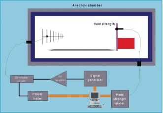
The main requirement of a radiated immunity test is to develop a constant, uniform field over the specific volume occupied by the EUT. If the field level is uniform and the EUT’s coupling to it invariant, then it is assumed that the test will exercise all the susceptibilities that need to be tested each time the procedure is carried out. The most thoroughly specified method of developing the field is from an antenna in a test chamber. This is described in IEC 61000-4-3 [7], for field strengths of 10V/m in the frequency range 80MHz to 1GHz, and uses the substitution method for calibration. The test set up is shown in figure 9.
The test is carried out in three stages:
1. Calibrate the field strength over a uniform area without the EUT present. 2. Replay power versus frequency for all orientations and polarizations, with the EUT present and aligned with the uniform area.
The reasoning behind this method is that the presence of an EUT inevitably upsets the uniformity of the RF field, especially at frequencies where the EUT is large compared with a wavelength. The advantage of the substitution method is that the field strength at any given point around the EUT is irrelevant for the test outcome. Since the field strength is calibrated without the EUT present, changes in field strength caused by the introduction of the EUT are circumvented.
In practice, a number of difficulties are encountered:
(i) The method relies on an area of uniform field strength being generated within which the EUT will be placed. The larger the EUT, the larger this area must be.
(ii)The standard specifies the limits of uniformity to be -0, +6dB over three quarters of the points at which the area is measured. This asymmetrical specification is to ensure that under-testing at any point does not occur, but by implication, over-testing of up to 6dB at some points and under-testing at others, is still a possibility.
(iii)The test must be performed in a screened chamber to avoid interfering with other radio services.
(iv)The walls of an untreated screened room would introduce reflections that would create deep nulls in the field pattern over distances of a half wavelength (1.875 m at 80MHz down to 15cm at 1GHz), which would severely distort the field uniformity. Anechoic material (carbon foam or ferrite tiles) which is effective over the whole frequency range must line all six surfaces of the chamber.
(v) The size of the uniform area depends on the directivity of the antenna used. To maximize the area, the antenna needs to be as far away as possible from the plane in which the field uniformity is measured.
(a)This has the advantage that the interaction between the EUT and antenna is minimized. (b)But, has the disadvantage that the further away the antenna is, more power output from the RF amplifier is required.
(vi)Modulation must be applied to the test signal. Since real disturbances are likely to be modulated in some way, and this effects the EUT’s response, the standard calls for the test signal be to modulated by a 1kHz sinusoidal tone at 80% modulation depth. Note that this increases the actual peak of the applied level by 1.8 times (18V/m rather than 10V/m) and means that the RF amplifier needs to be able to deliver a further 5.1dB of power.
(vii) The test signal must be stepped over the frequency range with a step size no more than 1% of the previous frequency. This works out at a minimum test time of about 15 minutes for each full sweep.
(viii)The EUT must be illuminated with both horizontal and vertical polarization on all four sides, making eight tests in all – taking around 2 hours to complete the set.
Using the set up shown in figure 9, the field strength and field uniformity was calibrated and the power response required from the RF amplifier was recorded. The same 32 input - 8 group analogue console, fitted with the digital control and communications, as used for the emissions tests (before modification), was placed in the area of uniform field. A single audio output was monitored using an Audio Precision A1, plus a power amplifier and loudspeaker. Replay of the pre-recorded power versus frequency data file was controlled by software.
The Audio Precision’s automatic gain
setting relays started chattering, as the first test run reached 100MHz.
The 1kHz tone was clearly audible since the level detected at the console
output was –35 dBu. All frequencies at which demodulation occurred during
the test run was recorded by the control software as shown in Table
Table 2
It was expected that the console might fail the radiated immunity tests and further investigation was suspended until after the basic modifications to solve the emission problems had been sorted out. Some weeks later, after the modifications described in section 3 were completed, the console was re-tested. This time, no interference was detected and the console passed the radiated immunity tests.
…continued from previous page.
6 Conducted Immunity Disturbances can be induced directly onto cables by voltage or current coupling (i.e. capacitive or magnetic coupling).
Direct voltage injection is the preferred method in IEC 61000-4-6 [8]. A particular coupling-decoupling network (CDN) is specified for each type of cable to be tested. Since this type of coupling is invasive, the method is usually restricted to testing power cables.
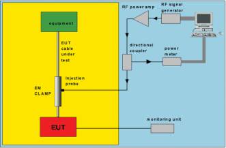
Bulk Current Injection (BCI) is an alternative method allowed in IEC 61000-4-6. The BCI probe is simply a current transformer whose primary carries the disturbance signal and whose secondary is the cable under test. The probe is halved and hinged, so that it can be clamped over the cable harness without having to break into it. The standard specifies that a substitution method be used: the power profile required to generate the required disturbance current into a fixed impedance calibration jig is recorded; the power versus frequency profile is then replayed with the EUT in place.
EM-Clamp injection is the third alternative specified in IEC 61000-4-6. The transducer is similar to the BCI probe but couples both inductively and capacitively at the same time. The use of ferrite absorber material allows a certain degree of isolation from the ancillary end of the cable. Most commercial EM-clamps are supplied pre-calibrated, so the clamp attenuation factor, or power profile can be entered directly into the control software.
Since I was having great difficulty in persuading my colleagues that a major change in grounding arrangements was necessary to achieve EM compatibility (at the time), I was extremely interested in the results that would be obtained from conducted immunity tests on audio input and output cables. The same unmodified 32 input - 8 group analogue console (fitted with digital control and communications circuits) was set up in the test chamber as for the emission tests, but one input cable was placed in an EM clamp, as shown in figure 10. A dynamic microphone was connected to one end of the cable as a source, with the other end connected to the microphone input on one of the 32 input channels. The channel was routed to a single output group and the gain was set to give a nominal speech output level of 0 dBu. The single console output was monitored using an Audio Precision A1, plus a power amplifier and loudspeaker.
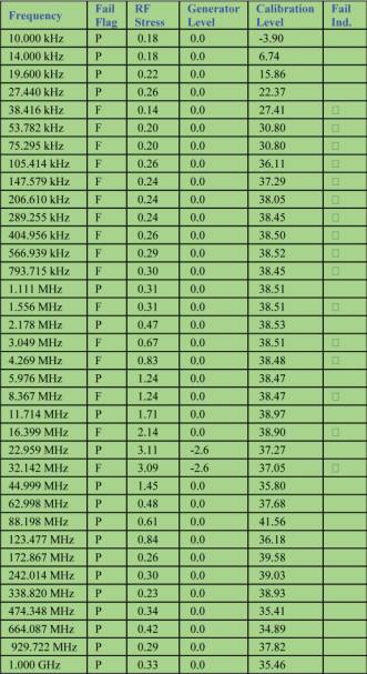
The console configuration, at the time of this test, was absolutely standard for a 1994 production model – “pin 1” connected to the PCB 0V trace and the chassis isolated from signal ground reference. Table 2.2, shows that the console system failed the test miserably. Each letter “F” on the chart indicates that the Audio Precision A1 detected the 1kHz modulation tone in the output. The interference tone markers represent output levels above –30 dBu, and so were clearly audible in the monitor loudspeaker. During the next few days, all input and output circuits were tested in the same way. This was to ensure that the problem was not being caused by some accidental circuit malfunction. Line level inputs were tested using a battery-powered oscillator unit (sine wave output turned off) as a source impedance, and output circuits were terminated by an Audio Precision A1 test set. The cable type used for the tests was changed several times, but to no avail. In each case, the resultant number of failures was the same.
Table 3
It was decided to modify a small number of the audio input channels by inserting an RFI filter between the input connector and the internal electronic circuit. The RFI filter consisted of two inductors, wound on a common ferrite core, plus two capacitors referenced to ground, connected on the circuit side of the inductors. The components selected for this test produced maximum attenuation at 80MHz (inductors) and 150MHz (capacitors), but the overall filter attenuation was excellent over the whole of the required frequency range.
The input channels were re-tested for CMRR (common mode rejection ratio), but the filter components had very little effect on the measurement. However, it was noted that for best CMRR results, adjustments should be made with the filter in place.
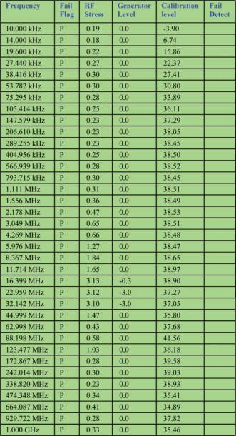
This time, the conducted immunity test results above 5MHz were excellent (table 2.3), but the RFI filter alone, could not absorb the interference below this frequency.
Table 2.3
The final solution to conducted immunity testing had to wait for several weeks. In order to test the next step in interference control, two modules were modified to simulate meshed grounding techniques. The original modules were fitted with insulated connectors so that the cable shields directly connected to the 0V trace on the printed circuit boards. New connector panels were manufactured and fitted to the modules, so that all connector “pin 1’s” could be mesh grounded with the shield of the signal cable under test. The early tests looked good, so all the modules in the console were modified with meshed ground techniques and RFI filters applied.
Table 2.4
Table 2.4 clearly shows the advantage of meshed grounding techniques – the interference induced in the cable shield is no longer detectable in the previously sensitive electronic circuits. Interference currents induced in the cable shield return to their source via the low impedance conductive plane formed by the grounded chassis.
Figure 11 shows how we implemented an RF backplane in a modular style console format. The modules have a conductive front panel holding the potentiometers and switches in place. All I/O connectors are mounted on a conductive rear panel which is mechanically bonded to the front panel - the main circuit board - and electrically bonded to the internal ground wiring and metal sub-frame via the module power and bus connectors. The module guide rails are also conductive and are mechanically bonded to the main frame structure. All other I/O connectors are mounted on conductive panels and mechanically bonded to the lower part of the frame.
Interference currents induced in the cable shield able to couple into the signal pair conductors are absorbed by filter circuits. Note that both filter and mesh ground techniques are required for a complete solution to conducted interference with respect to cables. Subsequent tests revealed that the lack of 360 degree shield bonding on the currently available XLR connectors puts an upper limit to interference control at about 1.2 GHz.
This all turns out to be common sense:
· A cable will behave as an antenna. · Connecting the cable shield to the internal circuit 0V conductor injects any noise current that couples to the cable directly into the circuit. · Connecting the cable shield to the equipment chassis (which is a common conductor for all local ground returns), diverts the interference away from the internal circuitry.
In the revised console design, a conductive back-plate was formed by introducing conductive module guides, so that all signal and control I/O connectors mounted on their individual metal panels were highly interconnected to form a practical interference bulkhead and signal reference ground. In all cases, the cable shield connections were bonded directly to the backplate for best transfer impedance performance.
The benefits of all this work was very clear in the very first EMC-production console. The absence of hum, buzz and click problems reduced the overall final testing procedures by a whole working day. We were always used to very low noise figures, particularly at the channel direct and group outputs, but the excellent figures were usually marred by processor clock noise that could be heard clearly above the background hiss. Now, processor clock noise or any other demodulated radio frequency noise was well below the level of the background hiss. The noise meter gain had to be increased by 20dB, to produce the same level of audible processor noise as noted in the original console design scheme test figures.
More good news followed after the console was delivered. The customer reported that the installation had gone very smoothly and that the only hum and buzz problems encountered had not included the console. This had saved them a lot of time.
During the following twelve months, there was a large reduction in system related fault reports and the words hum and buzz almost disappeared from fault report sheets. Customer feedback suggested that the many software error reports, that had plagued us for years, were almost certainly interference related, since they did not occur with the ‘new’ console design. Even the customer who insisted that “a mixing console would not work properly if the audio cable shields were connected to the chassis”, finally admitted satisfaction with his purchase. Production testing and installation of multi-frame consoles, which were previously a complete hum, buzz, click and software-fault nightmare, now became the same as testing or installing a single frame console.
Since our audio mixing console designs rely heavily on computer-controlled automation, similar conducted immunity tests were done on the digital control cables. A single example should suffice.
The main data communications cable, used to connect the console to the automation software running on an external PC, was placed in an EM clamp, as shown in figure 10. The automation software was programmed to step through a test routine that made incremental changes to the console status. The communications processor was running at 16 MHz.
The immunity test was performed again as described for the tests on audio input and output cables, but this time the console and computer were monitored visually as well.
(a)When the modulated RF signal reached 5 MHz, data recall errors appeared on the console. The test was paused and the communications processor on the console was reset. (b)The immunity test was re-started and the data recall returned to normal. As the modulated RF signal approached 8 MHz, data recall errors re-appeared on the console and the external computer program stopped running. Once more the test was paused while the console was reset and the software program was re-started. (c)At 16 MHz, everything stopped. The console and the computer were totally locked up and both items had to be powered down and re-started, before the test could continue. (d)Similar transient events to those noted in (a) and (b) above, occurred at 32 MHz and 48MHz.
The communications cable consisted of three shielded twisted pairs. All three shields were terminated at one end only. The two shields terminated at the console end were connected to the local 0V conductor of the logic power supply (the digital version of the pin 1 problem). The third shield was terminated on the ISA interface card mounted in the computer. This arrangement was chosen to minimize noise from the computer in the audio circuits. Since a large number of console systems had already been sold using the interface cards and cables, a solution using the same pin terminations was sought.
A solution was found after the console grounding structure had been changed to the mesh design outlined in section 3. Using a cable with three insulated shielded pairs, plus an overall shield, it was possible to keep the signal terminations the same. The overall shield, being 360 degree bonded to the chassis at both ends of the cable, completely solved the conducted interference problem and reduced the radiated emissions from the cable to negligible proportions. All other cables associated with data communications were found to require their cable shield conductors to be 360 degree bonded at both ends to minimize emissions and to obtain the best immunity characteristics. The advantage of these techniques became apparent later the same year, when it was noticed that the number of software error reports had almost disappeared. In fact they had been reduced to “real” software bugs. There is no doubt that many of the computer related fault reports that were attributed to software error were actually the system interfering with itself. A fourth advantage was immediately noticed when audio noise tests revealed complete freedom from computer generated noise.
7 Conclusion Using some of the test procedures and limits as set out in the product family standard for professional audio equipment, EN 55103-1 and -2, it has been possible to demonstrate the changes necessary in design philosophy and construction techniques required to achieve a system design with very low interference characteristics. The basic ideas set out here are not new and the underlying physics is well proven. The concept of using the conductive enclosure that contains the electronic circuits as the common reference ground for signals, internal circuits and safety - merely takes us back to the early pioneering days of electronic system design - before someone started using the ‘traditional’ techniques of star earthing and bonding cable screens to circuit 0V (not enclosure chassis) which we got stuck with for so long.
The ‘traditional’
method of bypassing the equipment enclosure and referencing the system
signal ground to the equipment’s internal power supply 0V conductor, has
been shown to be inadequate. This method of connecting the signal ground
to an apparatus -
Some people think that the shield current itself is a cause of hum noise, but this turns out not to be the case in practice. I finally found out why by performing some experiments in October last year, and these are described in [12]. Shield currents are only a noise concern for equipment that has the “Pin 1 problem”. Despite this problem being widely recognized in 1995 (see [1]) there is still a quite a lot of new and legacy equipment that suffers from it. Such equipment can usually be converted so that its cable shields bond correctly to its chassis.
The lack of a fully shielded enclosure was found not to be an insurmountable problem for high frequency interference control. The use of a conductive back-plate, containing all I/O connectors, to form an interference bulkhead, was shown to be excellent in controlling incoming and outgoing interference. However, it was necessary for the interference bulkhead to be highly interconnected to all other ground conductors in the system including all I/O cable shield conductors, the internal electronic circuit grounds and the protective ground. The large number of loops thus formed was shown to be advantageous in controlling high frequency interference phenomenon, without any low frequency penalties – hum and buzz no longer appeared, saving large amounts of time during console assembly/test, and during installation.
The very high frequency energy that can couple into signal conductors in cables due to the inadequacies in cable materials and construction, was controlled by using input and output filtering techniques. Further filtering of the AC power lines was found to be necessary to minimize low frequency interference conducted to and from the AC supply.
It was found that known interference sources inherent in the equipment design, such as digital control circuits, were best controlled at source. Ground and power planes proved to be excellent in controlling high level signal and clock pulse radiation by keeping the electric fields generated close to the printed circuit board. Careful demarcation and segregation between noisy and sensitive circuits and noisy and sensitive signal conductors proved to be essential.
All cables carrying information to and from the equipment under test were found to behave as antennas. The efficiency of the reception and transmission properties of the cables was directly linked to the grounding procedures used for the current return and shield conductors at each end of the circuit. When all current return and shield conductors were mesh bonded to a common conductor, the reception and transmission properties of the cables were minimized.
The inadequacies of single point grounding techniques were demonstrated to me in a very expensive exercise that happened in 1992. I was sent out to Toronto in order to solve an alleged console fault that was causing high levels of hum in a newly installed audio system. When I walked into the theatre, rehearsals were in progress, but the hum and buzz noise was clearly audible. Rehearsals were booked into the evening, so this meant that the “hum and buzz chase” would have to proceed overnight. The technicians were delighted, since they would get extra overtime pay. As soon as the rehearsal had finished, all input and output wiring was disconnected from the console. The hum stayed the same. Using a good quality audio test set, I checked out the console. The noise, CMRR and output balance figures were well inside the specification values. Anyway, since the hum and buzz could still be heard with the console disconnected, the problems must lie in some other part of the system.
Single point grounding techniques had been used for all the audio wiring (the cable shield connected at one end only). Several days had been spent in trying to achieve the lowest possible noise floor. No one could understand why we had hum in the system, since this was the widely accepted practice. So, we unplugged everything and starting at the amplifier-loudspeaker end, each cable was re-connected one at a time. As each input cable was plugged into its amplifier, hum started to build up, despite the fact that we knew that the outputs from the console were clean. Gradually, we became aware that the timbre of the hum was varying with the stage lighting state (the lighting department were there and still running through cues). Following the amplifier input cables back to the stage box revealed that they ran parallel with a bundle of lighting cables for about seven yards. When we separated the audio and lighting cables by about six inches, the hum was reduced to a very small amount. Although no hum loop current was flowing between the amplifier inputs and the console outputs, a whole set of AC mains and dimmer razz frequencies were coupling to the input cable shields by electromagnetic induction. With only one end connected to ground, the cable shields had all the required characteristics of an antenna, and duly delivered the received signal to each amplifier’s input connector. Since all of the amplifiers were designed with the “pin 1” problem, the hum and razz was directly injected into the 0V conductor of each one – and there were thirty two amplifier channels, each capable of delivering 500 watts RMS The buzz noise was quite loud!.
On a more recent occasion, I was asked to attend a touring installation to assist a new engineer in the vagaries of our show automation system. The company supplying the equipment was not only using one our latest consoles, but the main part of the rig consisted of loudspeaker controllers and amplifiers, chosen for their EMC compliance. When I arrived, the system was ready and working several hours ahead of schedule. The training session and then the booked rehearsal happened on time. The only complaints that day were from the crew, who had rather banked on extra overnight payments for chasing the expected hum loops.
While the EN 55103-1 and EN 55103–2 standards only apply to audio products put up for sale in the EEC, it has been demonstrated that these standards are very helpful in achieving designs for equipment that minimize the problems associated with a wide range of real-life interference, whilst automatically eliminating the problems with hums and buzzes that were once thought to be the price one had to pay for professional audio systems.
So it turns out that the techniques involved to meet the EMC directive produce an advantage for the equipment designer, the supplier and the customer.Designing equipment to meet EN 55103-1 and –2 should therefore be considered a financial necessity even in countries where lesser, or no EMC regulations exist.
References [1] Journal of the AES: Volume 43, Number 6, 1995.
[2] EMC for Product Designers: Tim Williams, Newnes, 1996.
[3] CISPR 16-1: 1993 Specification for radio disturbance and immunity measuring apparatus and methods: Part 1: Radio disturbance and immunity measuring apparatus.
[4] EMC for Systems and Installations: Tim Williams and Keith Armstrong, Newnes, 2000.
[5] EN 55103-1: Electromagnetic Compatibility: Product family standard for audio, video, audio-visual and entertainment lighting control apparatus, for professional use: Part 1: Emission
[6] EN 55103-2: Electromagnetic Compatibility: Product family standard for audio, video, audio-visual and entertainment lighting control apparatus, for professional use: Part 2: Immunity
[7] IEC 61000-4-3: 1995: EMC – Part 4 – Testing and measurement techniques – Radiated radio frequency electromagnetic field immunity test.
[8] IEC 61000-4-6: 1996: EMC – Part 4 – Testing and measurement techniques – Immunity to conducted disturbances induced by radio frequency fields.
[9] EN 55022: 1998: Information technology equipment – radio disturbance characteristics – Limits and methods of measurement.
[10] CISPR 17: 1981: Methods of measurement of the suppression characteristics of passive radio interference filters and suppression components.
[11] IEC 61000-5-2: 1997: EMC – Part 5 – Installation and mitigation guidelines. Section 2: Earthing and cabling.
[12] Bonding cable shields at both ends to reduce noise – Tony Waldron and Keith Armstrong – EMC + Compliance Journal – May 2002.
Tony Waldron is Technical Manager for CADAC Electronics PLC. Sound Designer at The Royal Danish Theatre in Copenhagen (1979-81) and Head of Sound at The National Theatre, London (1983-89). tony@cadac-sound.com http://www.cadac-sound.com/
|